|
|
Game Timerby Cathy Saxton 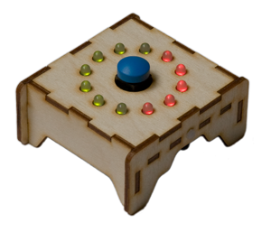
We get together with friends to play games on a semi-regular basis. One group plays a lot of games that require a timer. Those cheap little sand hourglass egg timers that come in games are terrible. They're hard to see and someone has to watch them carefully to see when the last grain falls. We often use a smartphone with a timer, but they have different interfaces which causes some confusion, and an expensive phone is at risk of being knocked off the coffee table or glopped with wine or bean dip. I used this as an excuse to work on a fun project: a game timer that would be easy to use, easy to see, less expensive than a phone, and less likely to be destroyed by a minor mishap. The timer turned out great, pretty much as I had envisioned it. Here's a description of its features:
One thing I'd like to note: this was a project for fun, not to save money; it's about $50 for the parts. The rest of this page describes the development process for the game timer. There are resources at the bottom of the page if you're interested in using this information as a starting point for your own projects. Project DesignI thought about how I wanted the timer to look and function and came up with the list of features above. I used that to compile a list of components that I'd need:
Before I could create a schematic, I needed to determine how I wanted to handle a couple of the features:
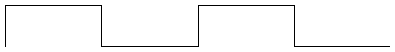
SoundWe can generate sound with a piezo buzzer by causing it to vibrate, which is done by toggling its input. The tone of the generated sound is determined by the frequency of the vibration. Higher frequencies are higher notes. The A note above middle C is 440 Hz. Each octave is a factor of 2, so the A note one octave higher is 880 Hz. (Each step, e.g. A to A#, is a factor of 12√2 = 1.059463.) Pure tones are sine waves, as is depicted in the first wave below. From the MCU, we generate a square wave, which works well enough to produce a recognizable tone.
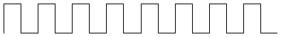
The volume is controlled by varying the width of the pulse. When the high and low portions of the wave are the same duration (50% duty cycle), the volume is loudest. The more they differ, the quieter the sound. It doesn't matter whether the high or low portion is longer. For example, 3% and 97% will result in the same (relatively quiet) volume. In the image below, each wave will produce the same tone since they are all the same frequency. The top wave will be the loudest since it has a 50% duty cycle. The second wave will be a bit less loud, and the last two will be the quietest in the group. Note that the last two represent the same volume level, just with high and low duration swapped. 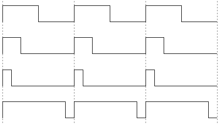
Perceived volume is based on a logarithmic scale; I noticed a difference in volume between widths of 1%, 2%, and 3%, but not between 48%, 49% and 50%. Microcontroller InterfaceThe Atmel AVR microcontrollers can automatically generate a (square) wave using a built-in Timer / Counter resource. The output from this counter can be sent to a MCU pin, so the circuit will want to have one of the outputs from a Timer / Counter connected to the piezo buzzer. Since we control volume in software (by altering the pulse width), we'll connect the volume knob directly to the MCU. We'll pair the potentiometer with a fixed resistor to create a voltage divider. Its output will be connected to one of the MCU's analog inputs. The MCU will read this voltage and use it to set the duty cycle on the square wave. CharlieplexingCharlieplexing is a technique for controlling many LEDs with relatively few MCU outputs. It is named after Charlie Allen at Maxim. Let's start with a quick review of LEDs and MCU control of them.
From this point forward, we'll temporarily ignore the resistor; we'll add it back in at the end. 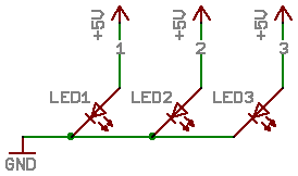
To control an LED with a microcontroller, we can connect the LED's anode to an output from the MCU. The image on the right shows three LEDs with anodes connected to MCU pins 1, 2, and 3. To light the LED, its anode is pulled high (as shown in this example). To turn off the LED, its anode can be grounded or put into a high-impedance state. In a high-impedance state, current is restricted from flowing, so the LED won't light. We can make an MCU pin high-impedance by configuring it as an input. Multiplexing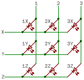
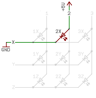
We can also connect an LED's cathode to an MCU output, and we can share the MCU's anode and cathode control lines across multiple LEDs, enabling us to control an array of LEDs. In the example on the right…
To light an LED, the MCU outputs high on the line connected to the LED's anode and grounds the line connected to the LED's cathode. All other MCU connections are put into a high impedance state (configured as input). In the example below, LED "2X" is lit by pulling line 2 high and grounding X. LEDs sharing a cathode line (X, Y, or Z) can be turned on together. In the following example,
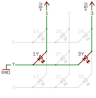
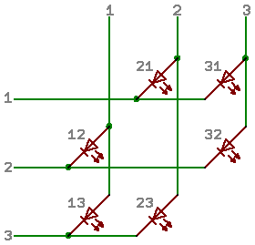
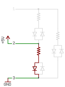
LEDs 1Y and 3Y are lit by pulling lines 1 and 3 high while Y is low. As you've probably noticed, we can't turn on all of the LEDs at one time. But, we can create the effect of having them all lit by rapidly cycling through the "strings" of LEDs. Each of X, Y, and Z will take a turn being grounded, with lines 1, 2, 3 optionally pulled high based on which LEDs in that string should be lit. If this is done rapidly, all of the LEDs appear to be on at the same time. Their brightness will be reduced since they are only on for a fraction of the time; in this example, 1/3 of the time (due to 3 cathode lines). CharlieplexingRecall the multiplexing diagram shown on the left below. We can use the MCU's lines 1, 2, and 3 for the cathode lines, too, eliminating the need for lines X, Y, and Z. When we do this, the LEDs on the diagonal are removed since they would have anode and cathode connected to the same MCU control line (and would thus never light). This new configuration – Charlieplexing – is shown on the right below.
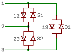
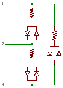
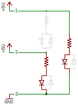
With our new Charlieplexing arrangement, you can see that 3 MCU lines can control 6 LEDs. All combinations of two control lines are used. The image on the right shows another representation of the same circuit, illustrating how pairs of control lines are connected to LEDs. So, how many LEDs can you control with n MCU lines? n × (n - 1) There are two ways to derive this formula:
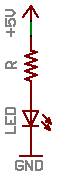
Adding Resistors – Simple Technique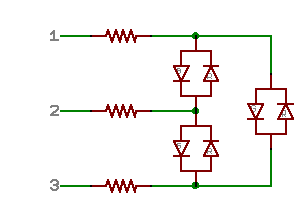
We need resistors to protect the LEDs from over-current. The image on the right shows a simple technique of adding a resistor on each control line. Let's explore how well this will work. 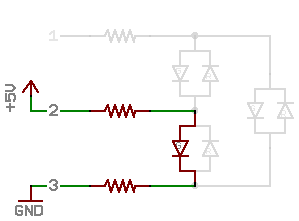
The image on the right shows an example of a circuit lighting a single LED. Given the following:
Solve for R (recall that V = I × R): 5 V = 2 V + 2 (10 mA × R) 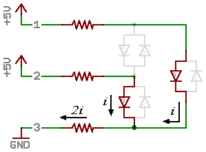
Now let's consider lighting two LEDs. In this case:
We want to solve for i (current): 5 V = i × 150 Ω + 2 V + 2i × 150 Ω Note that this is < 10 mA! With this method of placing resistors on each MCU control line, LEDs get less current and thus become dimmer as more LEDs are turned on at the same time. Fortunately, there's a better way to do this! Adding Resistors – Better Method
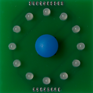
The limiting factor becomes the MCU's current-sourcing ability. When multiple LEDs are powered at once, the MCU has to source current for each LED. Even more constraining is that just one pin needs to sink the current from all of the LEDs illuminated at a time. If the current needs are too high, one possible solution is to program the sequence to have more steps and turn on fewer LEDs at a time. In this case, each line would take a turn as the cathode multiple times in the sequence. Game Timer ImplementationThe game timer has 24 LEDs (12 bi-color lamps). By using Charlieplexing, we can individually control those 24 LEDs with just 6 MCU lines. I chose 33 Ω resistors, placed in series with each lamp. This results in 33 - 85 mA per LED, depending on the battery voltage and LED voltage drop. With six lines each taking a turn as the cathode, each LED will be lit for 1/6 of the time, producing a brightness equivalent to approximately 5.5 - 14 mA. For the timing, I chose to give each cathode group a 0.1 ms period. The LEDs allow 140 mA at 1/10 duty cycle for a 0.1 ms pulse, so the LEDs should be happy. They get current slightly more frequently (1/6 duty cycle vs. 1/10), but at a maximum of 85 mA. The MCU allows a maximum 40 mA / pin, with max 200 mA total for all pins. I'm obviously exceeding the 40 mA limit when there are fresh alkaline batteries in the timer, but the MCU seems to be holding up fine so far. I expect that most stress to the MCU comes not from the anode pins sourcing current, but from the cathode pin, which sinks current from multiple LEDs in each string. With the circuit design and functionality of the timer, I've limited that to a maximum of three LEDs at a time (instead of the theoretical five). My hope is that the MCU will tolerate this because of the 1/6 duty cycle and since it is sinking instead of sourcing the large current. HardwareThere were four basic steps to creating the hardware for this project: documenting all the connections in a schematic, designing the board layout, having the board fabricated, and soldering items to the board. Schematic and PCB DesignI use EAGLE PCB design software for creating the schematic and board layout. Tips, files, and reference materials for EAGLE are on our EAGLE resources page. I started the schematic by adding all the components that I knew I'd use. Then, I considered the connections that I needed to make to the MCU. That imposed some constraints, but there was still plenty of flexibility.
I determined an arrangement of LEDs that had each MCU control line acting as cathode for four LEDs and provided a nice layout for optimizing the traces. I placed the symbols on the schematic in an arrangement that matched the layout I would use on the board. At this point, I had a rough idea of the MCU connections, so I worked on the printed circuit board (PCB) layout. Once I could see where each component was located relative to the MCU, I could pick among the available connection options. I wanted the timer to be fairly compact, so I expected the AAA battery holder to cover a large portion of the board. With the LEDs installed, their leads would poke through to the back of the board, but that would prevent the battery holder from resting flat against the board. It was also looking challenging to get all of the components squeezed into the small-ish footprint that I was envisioning. The solution was to use two boards. That gave me plenty of extra space and also enabled me to have a clean look on the top surface for the LEDs and buttons with no additional components – or even traces. 
For PCB fabrication, I sent Gerber files exported from EAGLE to Gold Phoenix PCB. SolderingThe MCU, resistor arrays, and a handful of resistors and capacitors are surface-mount components on the back of the bottom board. For that, I used a stencil to apply solder paste and then a griddle to heat the solder. My favorite method for making stencils is to use a cutting plotter. The remaining components were through-hole items, which were easily soldered with an iron. 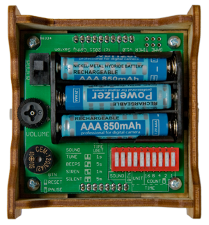
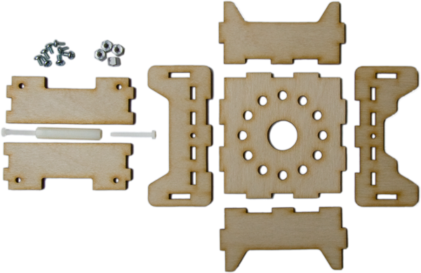
Box designI wanted a box to enclose the electronics and give the timer a more finished look. For various reasons, I decided that I'd create a design and have panels laser cut instead of using a pre-fabricated box. This gave me more flexibility on size and shape and ensured that I would have access to batteries and switches. The design criteria:
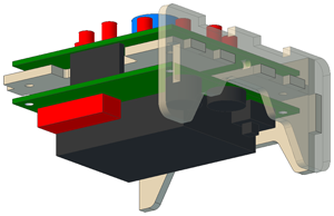
For the box, I'm using a common "sandwich" design: slots in the side panels hold the front, back, and mid-level panels in place via tabs, and the sides are held together with a long bolt. The picture on the right shows one of the side panels (it's the translucent panel on the right) and how tabs on the two mid-level panels and the back panel are mounted into slots on the side. I had planned to glue the top to the front and back panels, but it turned out that there's enough friction to keep it in place without needing any glue. For mounting the PCBs, I decided to attach the bottom PCB to a panel located between the two PCBs. In the picture above, you can see the mounting holes in the bottom PCB and the mid-level panel. The top PCB connects to the bottom PCB through headers making the necessary electrical connections. I ultimately just needed a 2D drawing for lasercutting, but decided to model in 3D to ensure correct vertical placement for the mid-level PCB-mounting boards and access to the volume knob. I used Alibre Design. For the 3D model, I first created parts for the PCBs including components, then created an assembly with the boards, and finally created the box panels directly in the assembly. For lasercutting, I created a drawing and inserted a "standard view" for each panel. Note that it's important to ensure that the scale is 1:1 for both the drawing and the insertions! I exported as DXF (AutoCAD 2004) to create a file to be used with the lasercutter. Here are the box panels and hardware: SoftwareState MachineThe main control code for the timer is a "state machine." It keeps track of the current state of the timer and checks for activities that would trigger a transition to a new state. There are numerous states, but they fall within four groups:
Transitions can be triggered by:
The main program loop has three phases:
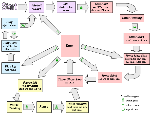
This flowchart shows the various states and the transitions between them. Microcontroller resourcesThe game timer board is using an Atmel ATmega48A, which has the following features:
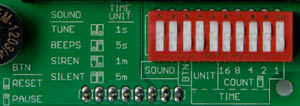
There are two ways for the software to learn about interesting activities – interrupts and polling. With an interrupt, an internal process of the MCU watches for the specified trigger and interrupts code execution to call a special function when the trigger happens. With polling, the software repeatedly checks for any changes that need to be handled. Each has its benefits and drawbacks. The game timer code uses both interrupts (for the timer) and polling (for button activity, transition times for LEDs and sound, and completion of an ADC conversion). Details are in the relevant sections below. ClassesClasses can help provide organization and encapsulation. The game timer code has a C++ class for each "object" (listed below). The implementation details are handled by private class code (and stored in a class-specific file). Callers don't need to know or understand details about the implementation; they just communicate with the class through a public interface that provides functions for the features supported by the class (e.g. 'play a tune', or 'is the tune still playing?'). Public interfaces and some implementation details for the classes are described below. It may be helpful to consult the MCU datasheet when exploring the code. DIP Switch class The public interface provides functions to:
The private class code deciphers the DIP switch settings. It knows which inputs to look at for each setting and how to interpret the switch positions. Timer class The public interface provides functions to:
The private class code sets up Timer/Counter 0 for measuring time:
Sound class The public interface provides functions to:
During idle loop processing, the sound class checks elapsed time for the current note and transitions to the next note (or stops playing) when appropriate. The private class code sets up Timer/Counter 1 to generate a waveform on the output pin. It uses the Fast PWM with Compare Match Output mode, which works as follows:
The tone determines the Prescaler and Top values (period / frequency). The volume level determines the Match value (pulse width). Recall that maximum volume is at a 50% duty cycle, i.e. when Match = Top / 2; the volume will be quiet for small (or large) Match values. Analog class The public interface provides functions to:

The private class code handles selecting the appropriate channel (volume or battery), starting conversions, and checking to see whether prior requests have completed. When responding to caller requests asking if a value has changed, the class code requires that the value has changed by a minimum tolerance. When an analog to digital conversion is made, it uses a "reference voltage." The result of the conversion is the ratio of the input divided by the reference voltage. When reading the volume level, we use Vcc (the voltage from the battery pack) as the reference voltage. Since the volume input is a voltage divider, comparing against the battery voltage ensures that a particular volume setting will always yield the same result, even as the battery voltage changes. When checking battery voltage, we use the internal 1.1 V reference voltage. The battery input comes from the voltage divider shown on the right. The input to the MCU will be at a voltage level equal to Vcc × 25/(25+77). This means that Vcc voltages of 4.49 V and higher will result in the maximum reading, with lower values produced as the voltage drops. LED class The public interface provides a function to let the caller specify which pattern to show. During idle loop processing, the LED class transitions to next "string" in the Charlieplexing cycle when enough time has elapsed. The private class code has a table of bytes that are the register values to use for each step of each pattern. Each pattern has six steps per cycle, one for each LED control line taking a turn being grounded (as the cathode). Each step needs to set direction register and output register bits as follows:
The direction output values for each step are calculated in an Excel spreadsheet and stored in program memory (Flash, not SRAM). The buzzer and start button also use the same register as the LEDs; the LED code maintains their states. Putting it All TogetherOnce I had the code all written and was ready to download and test it, it occurred to me that I'd forgotten to check the code size before selecting the MCU. I'd gotten the smallest (4k Flash) option when I'd ordered parts for the timer. It's a good idea to ensure that the physical parts match the dimensions from the spec sheets, so I like to get the parts and verify their sizes before ordering boards. Normally, I prototype with the biggest part, but for some reason I'd gone with the cheapest this time. I checked the program and discovered it was 6k bytes. I was not a happy camper! Being a few bytes over would be easy to solve, but it seemed unlikely that I could find 2k of extraneous stuff. I'd already soldered everything to the board and wasn't optimistic about the likelihood of being able to desolder the MCU without damaging other components. That meant that if I needed a larger MCU, I'd have to start over with a new board. Plus, of course, I didn't have any of the larger MCUs on hand. In general, I try to write small, efficient code. There are a few places where I choose maintainability over efficiency, but that has a minimal effect on code size. I checked the "release" build to see how much space I'd save when removing debug code, but that had a minimal impact. I considered whether I could trim down program-memory tables that I was using for things like the LED patterns and the timer end tune. Reducing these would mean that I'd lose some features, but I was getting desperate. It turns out that I'd only be able to save a hundred bytes or so (out of 2,000 needed). At that point, I decided to investigate what was taking up so much space in the code, so I looked at the .map file. Aha! There was a lot of space used for floating point functions! I was using floating point when making calculations for the sound volume; I had three assignments and four multiplications using 'float' variables. I changed to fixed point math and dropped from 6,248 bytes to 2,852! Yippee! This would have been a fun discovery if it had just been a cool optimization, but with the current state of the project, it was especially sweet.
Fixed Point MathFixed point math uses integers to represent fractions. There are two advantages to using integers: We don't need special libraries (all that code space!), and calculations are faster than with floating point (on MCUs). For a fixed point implementation, a constant denominator or "base," is chosen. Stored values are determined by multiplying the actual number by the base. For example, consider wanting to store dollars and cents. We'll choose 100 as the base. $1.23 is represented as 123. $2.90 is 290; $0.07 is 7; $13 is 1300. Addition and subtraction work as usual:
Note that a "carry" from fraction to whole number happens automatically (as does a "borrow"). For multiplication, one additional step is needed: the result must be divided by the base after doing the multiplication of the two fixed point values:
For Division, we first multiply the dividend by the base, then do the specified division:
Note that in the second example, the result is truncated; remember, we're using integer math! Fixed Point Math in the Game Timer For the implementation of fixed point math in the game timer, I chose a base (denominator) of 216. Powers of two are commonly used for the base because multiplication and division are simple bit shifts. I'm using a fixed point variable to store the fraction of the sound wave period when the pulse should be high (to set the volume level). This number is always less than one (since the maximum value will be half the pulse, i.e. 0.5). So, I just need a short (16 bits) to store my fraction. I multiply this fraction by the counter's Top value (period) to calculate the counter's Match value (pulse width). This calculation is made using a long (32-bits) in order to avoid overflow. Resources
|

| ©2000-2024 Idle Loop Software Design, LLC. You may not copy or reproduce any content from this site without our consent. |